Overview
In this post I will outline some lessons learned about my journey designing for and deploying the Cisco C9104 Marlin access point in our stadium.
Installation
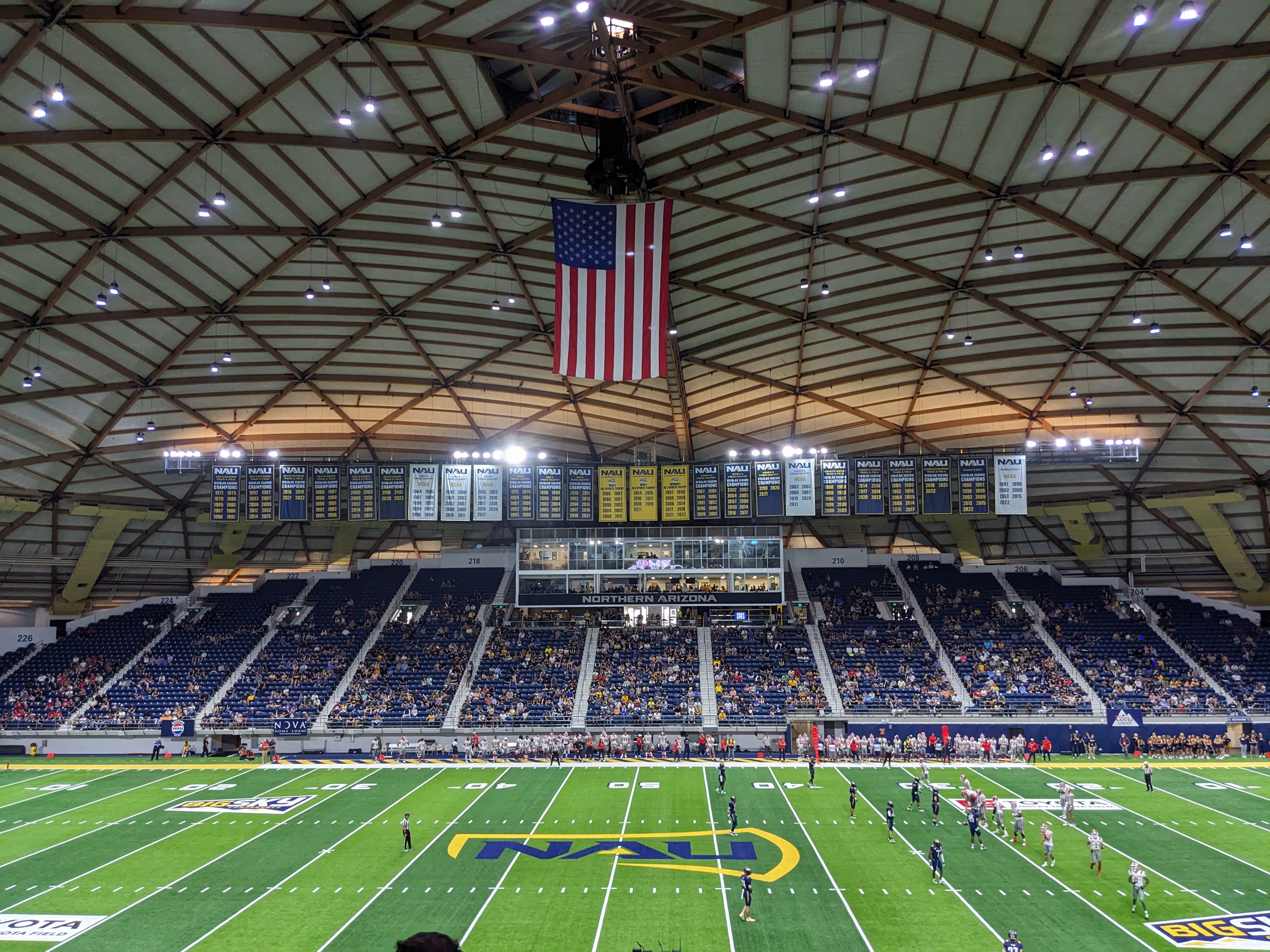
One of the many challenges of deploying wireless in a stadium is where to best mount the access points. There are many opinions on this matter with different preferences from wireless engineers depending on the design, layout, and mounting options.
In our final design, we chose to use the catwalk to mount the access points facing the stands, but one thing I hadn’t previously considered was the catwalk’s weight capacity. The last thing I wanted weighing on my conscience,no pun intended, was the catwalk collapsing under the added load during an event.
To handle the anticipated wireless density in the stands, our design called for an estimated 14 to 16 access points to be mounted on the catwalk, with two access points directed at each seating section, one angled toward the lower seating area and the other toward the upper. However, with each access point weighing 15 pounds, it was crucial to verify the weight capacity of the floating catwalk before adding up to 240 pounds of additional equipment.
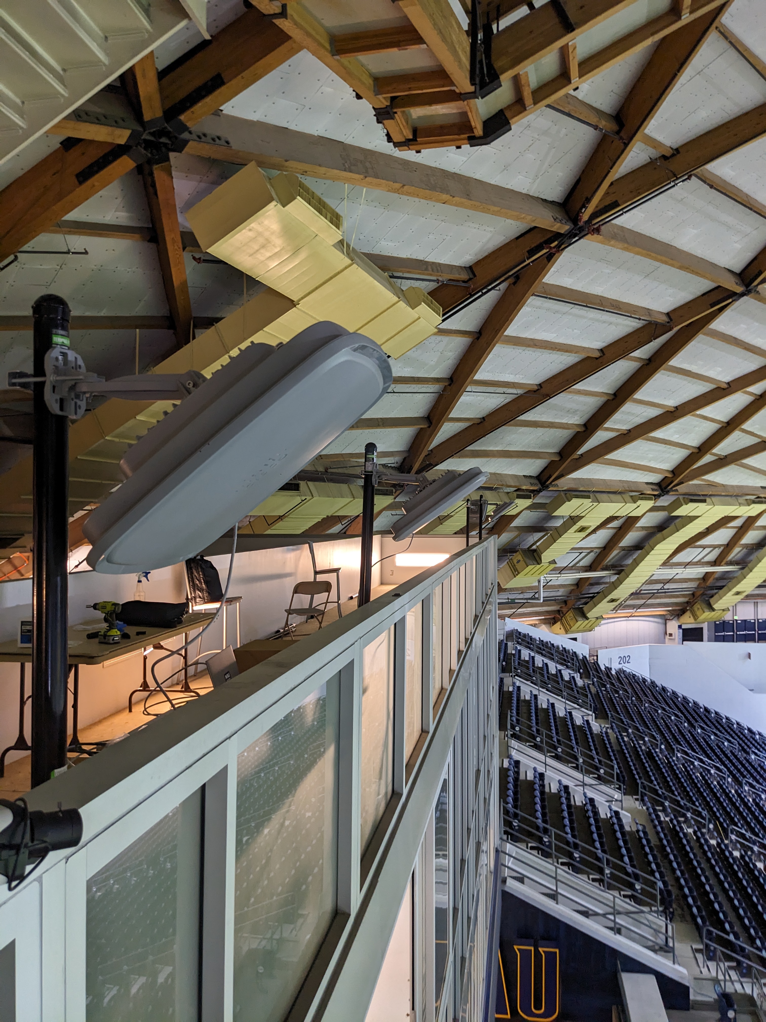
We haven’t completed the installation of the access points on the catwalk just yet, but as a proof of concept, we temporarily mounted them above the press boxes to provide coverage to the seating sections below.
The image below shows our improvised setup, each access point was secured to a metal “sled,” consisting of a vertical pole mounted to a base, which was weighed down with cinder blocks for stability.
A big shoutout to the student employees who hauled those cinder blocks up stairways and ladders to get everything in place, the true unsung heros of the project. The effort was almost reminiscent of the Egyptians building the pyramids but under slightly less harsh environments and with pay.
Channel Issue
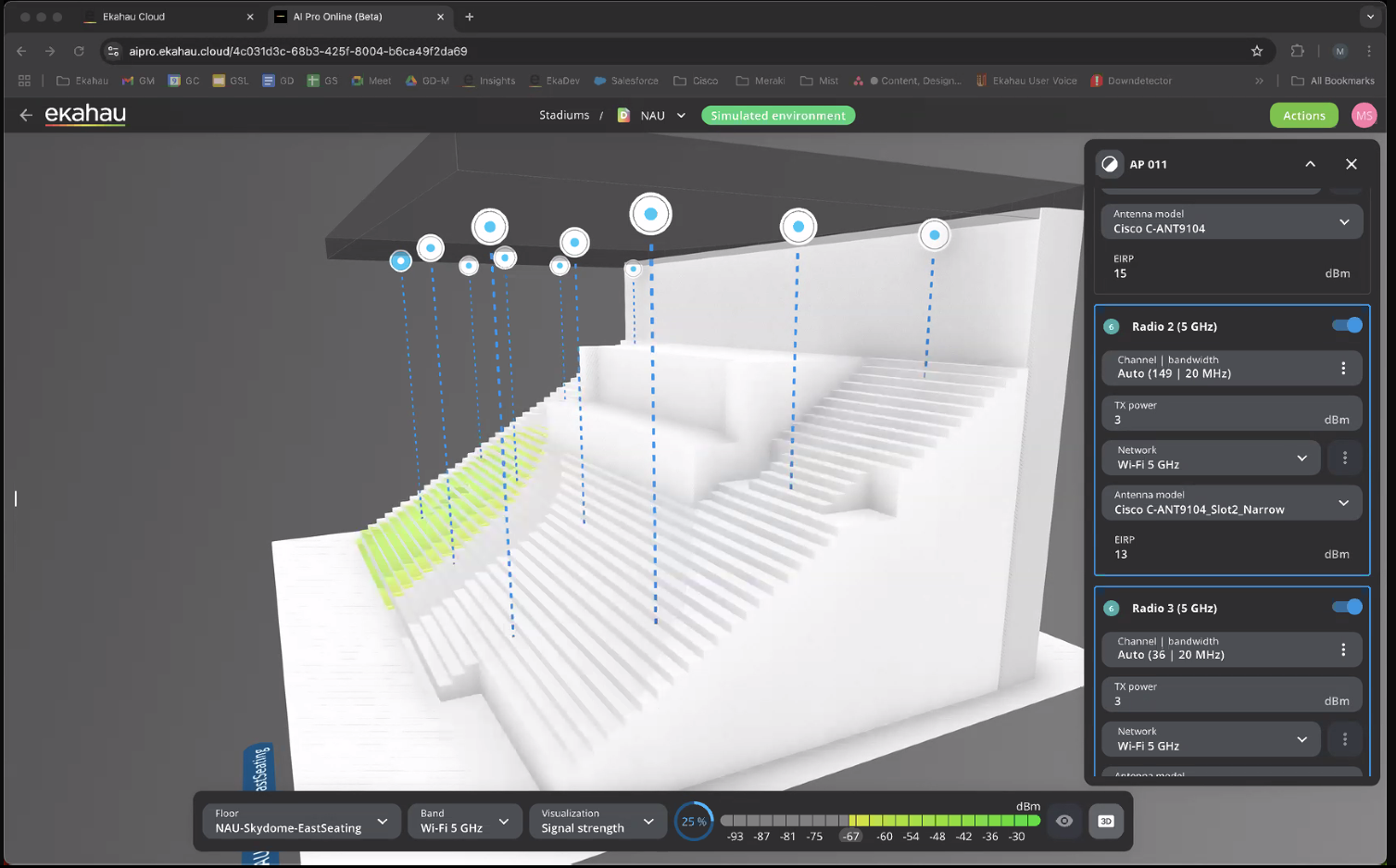
One issue we discovered during the deployment of the C9104 access points was that Radio Resource Management (RRM) was not supported on these units. This meant we had to manually specify the channel selection and TX power for each radio, each access point using dual 5 GHz radios. Depending on the number of units deployed, this process can become quite cumbersome. However, this limitation is a byproduct of the access point’s design, which intentionally disabled RRM to mitigate side-lobe RF interference and maintain tight signal patterns.
3D Plans
A massive shout out to Matt Starling over at Ekahau for using our stadium floor plan in the introduction of their 3D slopped floor simulation feature announced on their 04/10/25 webinar.